Monthly Archives: November 2019

Four Pole Resonant Filter

The slope of a one pole filter is -6 dB per octave. A steeper slope can be achieved by connecting multiple one pole filters in series, and giving all of them the same frequency coefficient. It was Robert Moog who developed this technique for synthesis, using four low pass filters in series to make his voicing filter for the Moog 904A filter module in 1966. This filter arrangement (aka ladder filter) has been used in all subsequent Moog synthesizers, as well as most other analog and virtual analog synthesizers.

Moog’s filter has another characteristic that makes it especially flexible. It has a regeneration control (later emphasis) which transforms the low pass filter into a resonant band pass filter, and then a sine oscillator when regeneration is fully on.

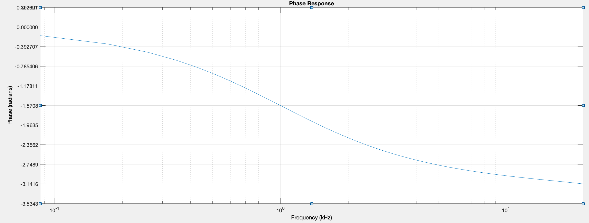
This regeneration control is a negative feedback control, mixing the inverted filter output back into the input. As the control is increased, the low frequencies passing through the filter are reduced, and the signal around the filter frequency is increased. To understand why this happens, consider the frequency and phase response of the low pass filter at 1000Hz.

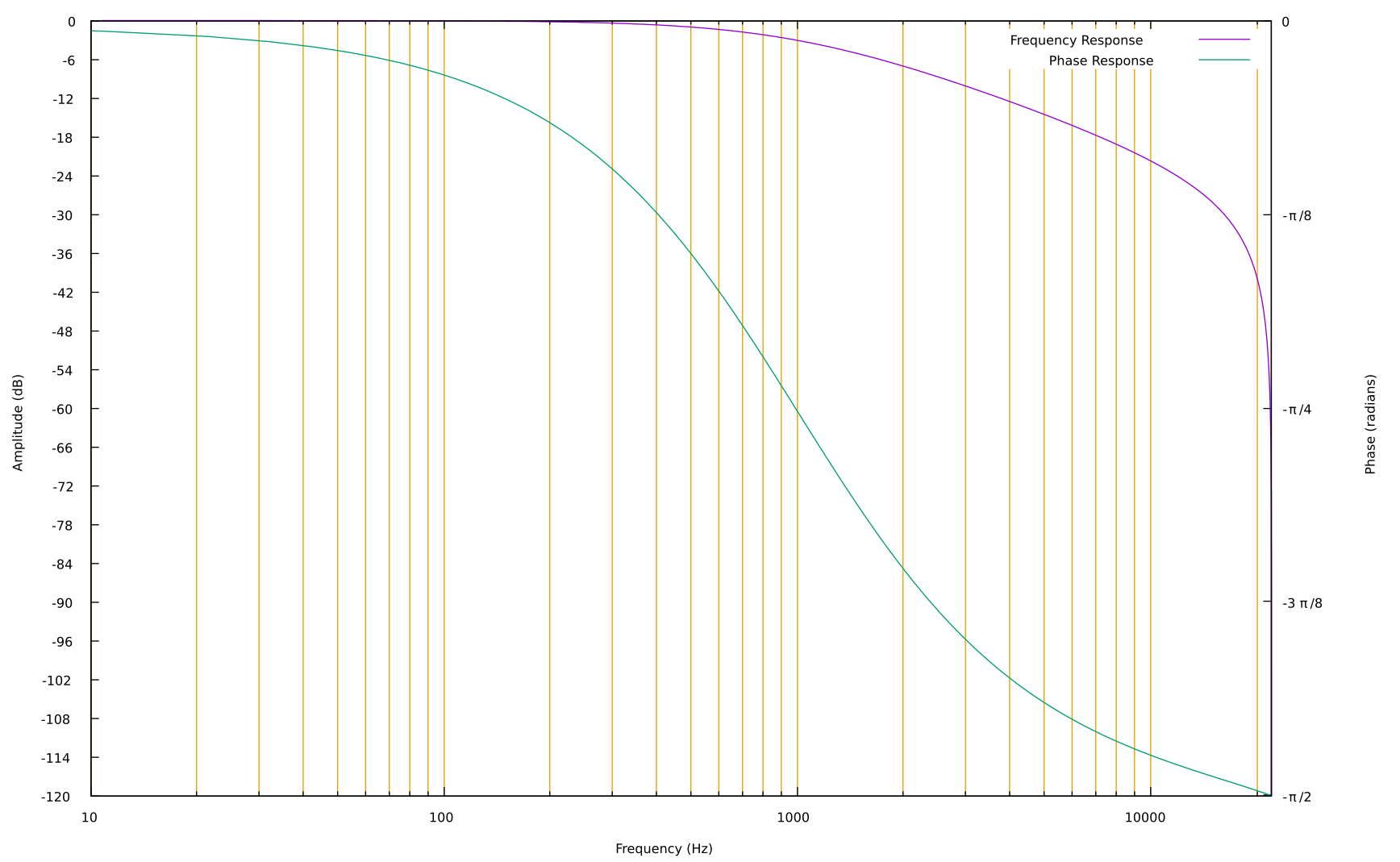
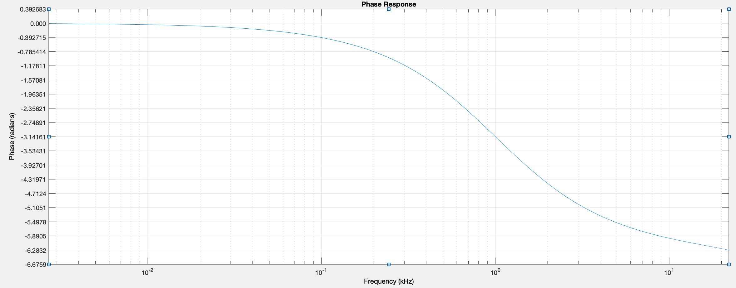
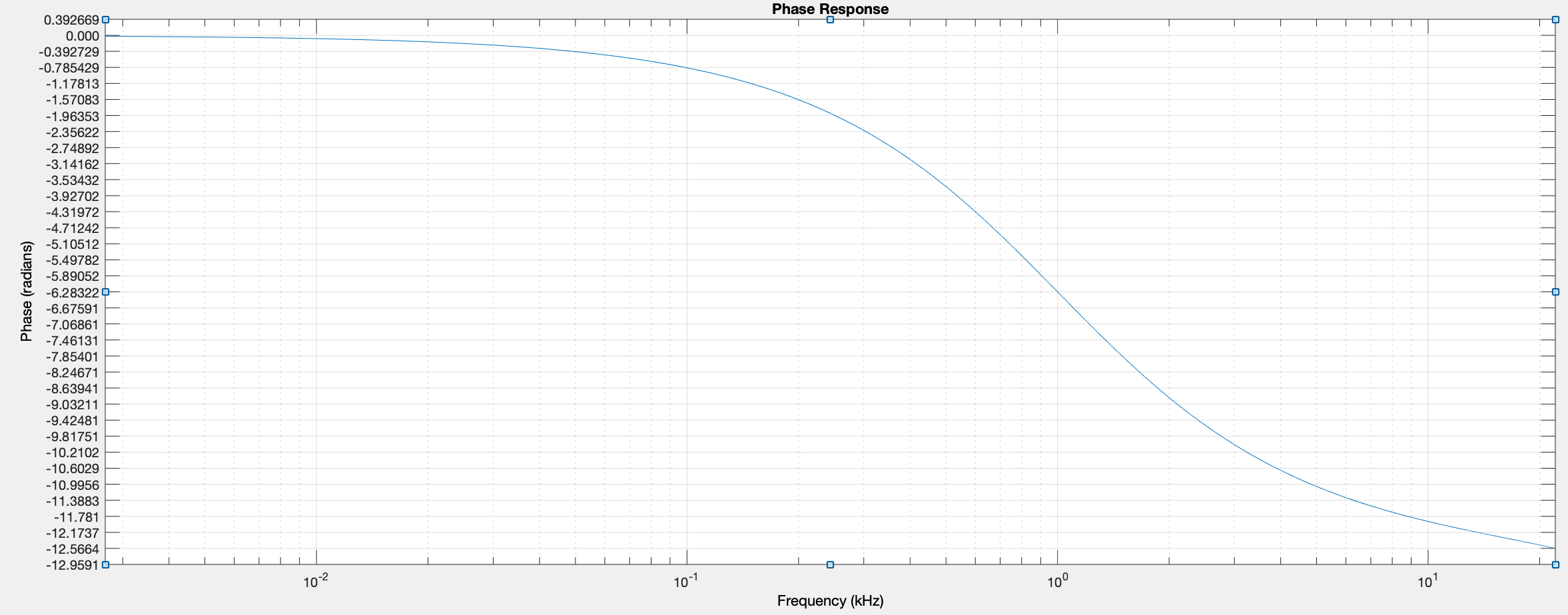
At 1000Hz, the phase shift is -π/4 and the gain is -3dB. When 4 of these filters are in series, the total phase shift at 1000Hz is -π and the gain is -12dB. A phase shift of -π is a signal inversion at this frequency. If the inverted signal at 1000Hz is inverted again, it will be in phase with the input. By mixing it with the input, the signal at 1000Hz is reinforced.

Below 1000Hz, phase shift moves toward 0. The filtered signal below 1000Hz becomes more in phase with the input signal. By inverting it and mixing back into the input, the sound below 1000Hz will be reduced.

Finally, as regeneration increases, feedback in the filter increases. The sound becomes more resonant – the filter “rings”. In short, by reinforcing the signal at the filter frequency, reducing the signal below the filter frequency, and increasing the filter feedback; this filter moves from being a low-pass filter to a resonant low-pass to a band-pass filter and finally a sine wave oscillator. This is what makes Robert Moog’s design so clever and useful.

Implementation

The C implementation is almost as simple as the description above. The only addition is a saturation section after the negative feedback is added to the input. One could also add saturation after every filter section to emulate the natural saturation in the original transistors. One note: because of the delay in the feedback loop, this implementation of the Moog ladder filter will get slightly out of tune at higher frequencies. There has been some good research in eliminating this feedback delay error. If you want to dig deeper, read Vadim Zavalishin’s The Art of VA Filter Design.

double out1a, out1b, out1c, out1d; // keep track of the last output

ladderFilter(float *input, float *output, long samples, float cutoff, float regeneration) 
{
    double c = exp(-6.283185307179586 * cutoff/samplingRate);

    for(int i = 0; i < samples; i++) 
    {
        float in = *(input+i) - (out1d * regeneration);
        in = 0.636619772367581 * atan(in); // constant is 2/π
        out1a = in * (1 - c) + out1a * c;
        out1b = out1a * (1 - c) + out1b * c;
        out1c = out1b * (1 - c) + out1c * c;
        out1d = out1c * (1 - c) + out1d * c;
        *(output+i) = out1d; 
  }
}

2 random pitch sawtooth waves into 4 pole ladder. regeneration increasing through clip

Phase Shifter Derived from Cascaded Allpass Filters

An analog phase shifter (or phaser) is one or more notch (band reject) filters modulated by a slow triangle or sine wave. It’s a fairly common effect, often used on guitar (Something About Us by Daft Punk) or keyboard (Are You All the Things by Bill Evans). The main character of the phase shifter is that of a quickly changing timbre, much like the sound of a Leslie rotating speaker. As it uses a moving notch filter, only a few of the harmonics are affected at any moment. Popular phasers include the MXR Phase 90, the Mu-Tron Bi-Phase, and the Electro Harmonix Small Stone.

Phase shifters are made by using a series of cascaded allpass filters, with the output of the last filter mixed with the input signal. The highest frequency should be shifted by a multiple of 2π and the lowest shifted by 0 in this group of allpass filters, so that the input and output signals are in phase at the top and bottom of the spectrum, and reinforce when mixed together.

Implementation

The first order allpass filter introduced earlier can be used for the cascaded filters in a phase shifter. As the first order allpass filter has a phase shift of π at nyquist, 2 of these filters are needed to obtain a phase shift of 2π.

first order allpass: -π/2 at 1000Hz, -π at nyquist
2 cascaded allpass: π at 1000Hz, 2π at nyquist

All of the filters in the cascade will have their frequency modulated by the same oscillator. This will move a -π (180) phase shift point up and down through the spectrum. When mixed with the input signal, the -π shift point will create the notch.

If more filters are cascaded, more notches will be created. Sounds at 0, -2π, -4π, -6π, etc. will be reinforced, and sounds at -π, -3π, -5π, etc. will be cancelled. The extra notches will create a deeper, more obviously effected sound, as more harmonics will be removed by the notches. Also important: the multiple notches are no longer harmonically related, and so the phase shifter will not act like a resonant comb filter.

4 cascaded allpass: -2π at 1000, -π around 400Hz, -3π around 2500Hz
funky drummer original
funky drummer through 4 stage phase shifter swept from 200 to 5000 Hz

To put this together in C, a slow sine wave is needed. This will modulate the frequency of 4 cascaded first order allpass filters. The output of the last allpass filter will be mixed with the input signal.

// the samplerate in Hz
float sampleRate = 44100;
// the frequency of phase modulation - once every 2 seconds
float frequency = 0.5;
// initial phase
float phase = 0.0;
// x1 and y1 for each allpass stage
double x1a, x1b, x1c, x1d;
double y1a, y1b, y1c, y1d;

void Phaser(float *input, float *output, float frequency, long samples)
{
    long sample;
    float apfreq, tf, c;
    // calculate for each sample in a block
    for(sample = 0; sample < samples; sample++)
    {
        // get the phase increment for this sample
        phaseIncrement = frequency/sampleRate;

        // calculate the allpass frequency (200 to 5000) 
        apfreq = (sin(phase * 6.283185307179586) + 1.0) * 2400.0 + 200;
        // calculate the allpass coefficient
        tf = tan(3.141592653589793 * apfreq/sampleRate);
        c = (tf - 1.0)/(tf + 1.0);

        // compute the 4 allpass filters, and save the previous input
        float x0a = *(input+i);            
        y1a = (c*x0a) + x1a - (c * y1a);
        x1a = x0a;
        y1b = (c*y1a) + x1b - (c * y1b);
        x1b = y1a;
        y1c = (c*y1b) + x1c - (c * y1c);
        x1c = y1b;
        y1d = (c*y1c) + x1d - (c * y1d);
        x1d = y1c;

        // calculate the output for this sample
        *(output+sample) = *(input+sample) + y1d; 

        // increment the phase
        phase = phase + phaseIncrement;
        if(phase >= 1.0)
            phase = phase - 1.0;
    }
}

Decimation

Decimation is a type of waveshaping that reduces the resolution of the input signal by eliminating the lower bits in the integer representation of the sample. For example, lets take a sample of value 0.5337 (within the typical range of 1.0 to -1.0) to 3 bit resolution. With 3 bits, we only have 8 values from -1.0 to 1.0: -1.0. -0.75, -0.5, -0.25, 0.0, 0.25, 0.5, 0.75. The value 0.5337 becomes 0.5 (as do all values between 0.5 and 0.75). This reduction in resolution will create noise which is not related to the amplitude of the signal. The less bits used, the great the decimation noise. If we consider 3-bit decimation a transfer function, it would look like this:

3 bit decimation transfer function
sin(2πx) after 3 bit decimation

Using a transfer function like the above is one method of decimation. However, as with other types of waveshaping, it is more efficient to compute decimation directly, using the equation which would create the transfer function.

Implementation

The following equation could be used to decimate a floating point signal.

y[n] = \lfloor(x[n] * 2^{(bits - 1)})\rfloor/(bits-1)

Below are two C implementations of decimation to 3 bits. First using multiplication and division, and the second using logical bit operations. The logical operations are probably much less CPU intensive.

// decimation to 3 bits using multiplication and division

factor = pow(2.0, bits - 1.0);
output = floor(input * factor)/factor;

// decimation to 3 bits using logical operations

// convert to 16-bit sample
input16 = (int)(input * 32768);
// zero out all but the top 3 bits using bitwise and
// binary literals only allowed in gcc, in hex use 0xe000
output16 = input16 & 0b1110000000000000; 
// convert back to float using 1/32768
output = output16 * 0.000030517578125;

The first technique is more clear, and more flexible. It is also probably not that much more CPU intensive. Finally, the first technique could use a floating point value for bits, and this would allow continuous change from one bit depth to another.

FM tone progressively decimated from 6 to 1 bit.

When using decimation on recorded audio, you will notice that there is always distortion in the audio, and also that at low bit depths only the loudest sounds will be audible.