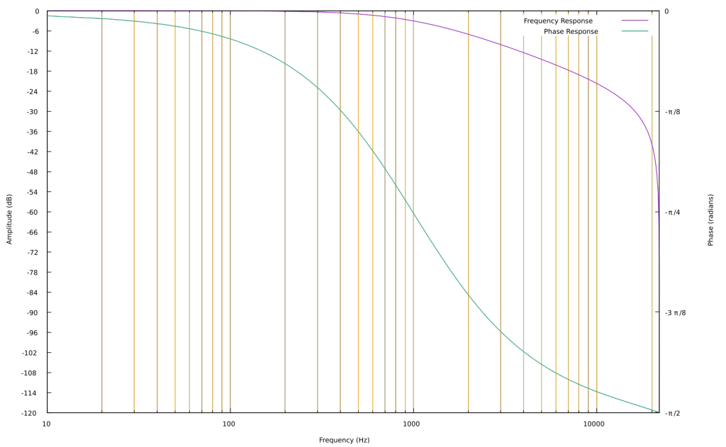
The slope of a one pole filter is -6 dB per octave. A steeper slope can be achieved by connecting multiple one pole filters in series, and giving all of them the same frequency coefficient. It was Robert Moog who developed this technique for synthesis, using four low pass filters in series to make his voicing filter for the Moog 904A filter module in 1966. This filter arrangement (aka ladder filter) has been used in all subsequent Moog synthesizers, as well as most other analog and virtual analog synthesizers.
Moog’s filter has another characteristic that makes it especially flexible. It has a regeneration control (later emphasis) which transforms the low pass filter into a resonant band pass filter, and then a sine oscillator when regeneration is fully on.
This regeneration control is a negative feedback control, mixing the inverted filter output back into the input. As the control is increased, the low frequencies passing through the filter are reduced, and the signal around the filter frequency is increased. To understand why this happens, consider the frequency and phase response of the low pass filter at 1000Hz.

At 1000Hz, the phase shift is -π/4 and the gain is -3dB. When 4 of these filters are in series, the total phase shift at 1000Hz is -π and the gain is -12dB. A phase shift of -π is a signal inversion at this frequency. If the inverted signal at 1000Hz is inverted again, it will be in phase with the input. By mixing it with the input, the signal at 1000Hz is reinforced.
Below 1000Hz, phase shift moves toward 0. The filtered signal below 1000Hz becomes more in phase with the input signal. By inverting it and mixing back into the input, the sound below 1000Hz will be reduced.
Finally, as regeneration increases, feedback in the filter increases. The sound becomes more resonant – the filter “rings”. In short, by reinforcing the signal at the filter frequency, reducing the signal below the filter frequency, and increasing the filter feedback; this filter moves from being a low-pass filter to a resonant low-pass to a band-pass filter and finally a sine wave oscillator. This is what makes Robert Moog’s design so clever and useful.
Implementation
The C implementation is almost as simple as the description above. The only addition is a saturation section after the negative feedback is added to the input. One could also add saturation after every filter section to emulate the natural saturation in the original transistors. One note: because of the delay in the feedback loop, this implementation of the Moog ladder filter will get slightly out of tune at higher frequencies. There has been some good research in eliminating this feedback delay error. If you want to dig deeper, read Vadim Zavalishin’s The Art of VA Filter Design.
double out1a, out1b, out1c, out1d; // keep track of the last output

ladderFilter(float *input, float *output, long samples, float cutoff, float regeneration)
{
    double c = exp(-6.283185307179586 * cutoff/samplingRate);

    for(int i = 0; i < samples; i++)
    {
        float in = *(input+i) - (out1d * regeneration);
        in = 0.636619772367581 * atan(in); // constant is 2/π
        out1a = in * (1 - c) + out1a * c;
        out1b = out1a * (1 - c) + out1b * c;
        out1c = out1b * (1 - c) + out1c * c;
        out1d = out1c * (1 - c) + out1d * c;
        *(output+i) = out1d;
  }
}
