
Tremolo
In DSP, tremolo (not to be confused with vibrato) is a periodic amplitude variation of a signal. Most often, it appears in the form of a sine wave that subtracts from the amplitude of the signal, though technically any waveform could be used. “Classic” tremolo can be charactarized as having two parts: speed and depth which are the frequency of the sine wave (modulator) and the degree to which it modifies the signal its being applied to (the modulators amplitude). It is, essentially, a very slow amplitude modulation.
Technique
What needs to happen is to create a new signal such that if the depth of the tremolo is 0.5, the signal we multiply to the carrier oscillates between 1 and 0.5. If the depth is 0.25, then it must oscillate between 1 and 0.75, and so on. The equation we follow is:
S_{m} = 1 - d \bigg( \frac{S_{sin}}{2} + 0.5 \bigg)Where:
Sm is the modulator (the signal that makes the tremolo effect)
Ssine is a sinewave input (oscillating between -1 and +1)
d is the depth of the tremolo between 0 and 1
This assumes that the frequency of the tremolo signal, Ssine, is set when generating that signal.
Implementation
For the input signal (signal we want tremolo on), let’s use a guitar chord:
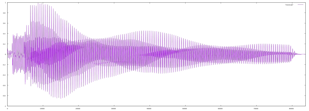
[Listen]
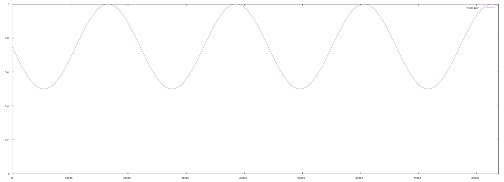
For a tremolo with a depth of 0.5 and a frequency of 2Hz, we get the following:
When we multiply the input and the tremolo together, we get:
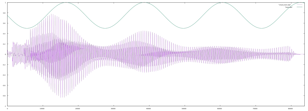
In this plot, the tremolo signal and the output are superimposed to show the relationship.
[Listen]
Autopan
An autopan effect can be created with a slight modification of our tremolo effect. The input signal will be sent to both left and right output, with gain controls on each. To make the signal appear in the center, the gain will be 0.5 for both outputs. To appear on the left, the gain will be 1.0 on the left output and 0.0 on the right output. As the left gain and right gain add up to 1.0, the right gain can be calculated as 1.0 – left gain. By using a sine wave (or other low frequency oscillator) for the left gain, an autopan effect is created. Simple C code for this effect is below.
// the samplerate in Hz
sampleRate = 44100;
// the frequency of autopan - once every 2 seconds
frequency = 0.5;
// initial phase
phase = 0.0;

void Autopan(float *input, float *outputL, float *outputR, float frequency, long samples)
{
    long sample;
    float leftgain, rightgain;
    // calculate for each sample in a block
    for(sample = 0; sample < samples; sample++)
    {
        // get the phase increment for this sample
        phaseIncrement = frequency/sampleRate;

        // calculate the gain factors
        leftgain = (sin(phase * 6.283185307179586) + 1.0) * 0.5;
        rightgain = 1.0 - leftgain;

        // calculate the output for this sample
        *(outputL+sample) = *(input+sample) * leftgain;
        *(outputR+sample) = *(input+sample) * rightgain;

        // increment the phase
        phase = phase + phaseIncrement;
        if(phase >= 1.0)
            phase = phase - 1.0;
    }
}