STM now offers a customized version of Eclipse which is configured with the compiler, debugger and other tools (the toolchain) for STM programming as well as STLink, the software which enables a link to the STM32F hardware through USB. This IDE will work with any of the STM32F discovery boards and includes CubeMX, a simple code generator which builds the initial project.
The IDE can be downloaded from this page: https://www.st.com/en/development-tools/stm32cubeide.html . If the link changes, you should be able to find it by searching for STM32CubeIDE on the www.st.com website. You will need to create an account on www.st.com to download.
You will find installation instructions on the STM32CubeIDE under “Resources”. Click on “Resources” then “User Manuals” and you will find “STM32CubeIDE installation guide” (PDF). Download and open. At this point it will be useful to download the “STM32CubeIDE quick start guide” as well. Follow the installation instructions: install STLink first, then the IDE (do not delete the installer after installing STLink). If on macOS you may need to bypass Gatekeeper by holding down the option key when opening the installer, and the IDE for the first time. If all goes well, you will be able to start STM32CubeIDE. Under macOS, if it complains that STM32CubIDE is corrupted when starting it, you may have to clear the file attributes of the app. This is done by entering
sudo xattr -rc /Applications/STM32CubeIDE.app
in the Terminal app, and entering your password when prompted.
Setting up a sample project
There are several videos on youtube showing the creation of a sample project. I found the one from STM (“How to use STM32CubeIDE”) to be most complete: https://www.youtube.com/watch?v=eumKLXNlM0U. Use this video as a guide to creating your sample project and learning the compiler and debugger. However, be aware that some of the videos on line are already out of date.
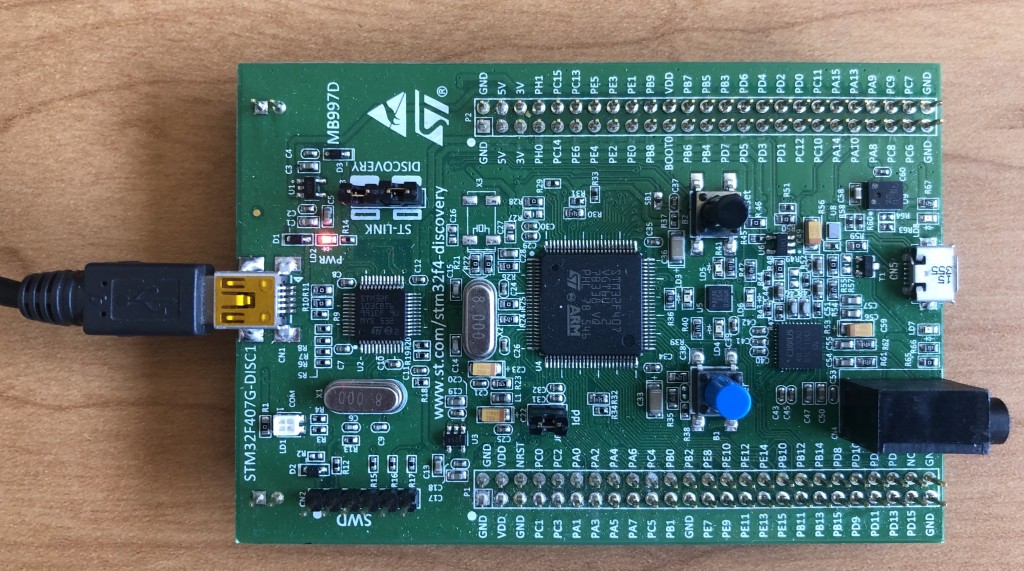
I will be describing a project for the STM32F4 Discovery Kit. Before starting, attach the discovery board to the computer with the miniUSB jack (not the microUSB jack). The miniUSB is used for application loading and debugging.
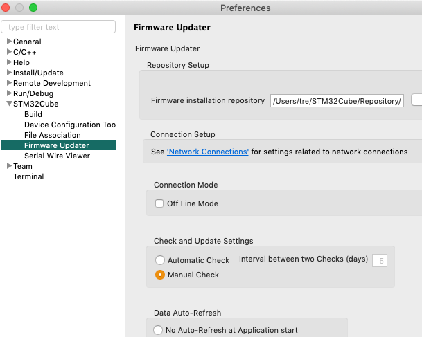
When initially creating an STM32 project (“New:STM32 Project” in “File” menu), the IDE will download an update. If this gets stuck, you will need to force quit STM32CubeIDE, re-open, and set Preferences:STMCube:Firmware Updater to “Manual Update.” You may also need to disable automatic updates in “Install/Update.”
You should now be in the Target Selection window. Click “Board Selector” and select “STM32F4Discovery” (about 3/4 down the list). Click “Next”, and enter a project name (“LED blink” would be good). Options should be “C”, “Executable” and “STM32Cube.” Click “Next.”
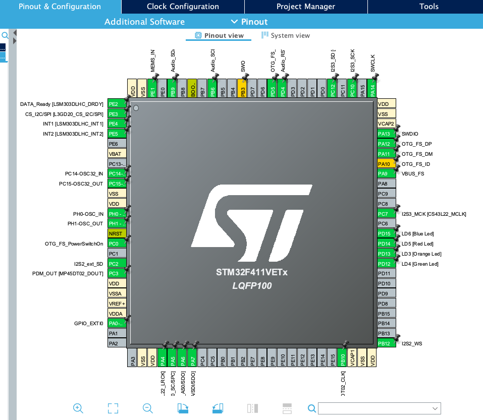
Now we will be in the Device Configuration Tool. In the STM32 each pin can be used for multiple functions (flashing LEDs, communicating to CODECs, PWM, USB, etc.). This tool allows us to specify what each pin is used for, and in most cases it will generate code to use the pin in the desired way.
For our first example, we won’t be changing anything from the default. Under the “Project” menu select “Generate Code.”
To get started, we will insert code to blink the blue and red LEDs. The youtube video above shows how to do this at 1:30+. Under the left panel “Project Explorer” open your project and under that open the “Src” arrow. Double click on main.c to open this file in the editor.
Scroll down to the main(void) function. At the end of the function there is a while(1) loop. We will add some STM specific functions that come from the HAL (hardware abstraction layer) library. Before the line /* USER CODE END WHILE */ add:
HAL_Delay(200);
HAL_GPIO_TogglePin(LD5_GPIO_Port, LD5_Pin);
HAL_GPIO_TogglePin(LD6_GPIO_Port, LD6_Pin);
HAL_Delay waits a number of milliseconds before the next instruction. HAL_GPIO_TogglePin changes the output voltage of a pin from high to low or low to high. The port and pin numbers are found in main.h, which is found under the “Inc” arrow in the project. These pin and port numbers are specific the STM32F4Discovery board.
Now we can save, compile, download and run the program on our STM32F4Discovery board. Save main.c, and select “Debug” under the “Run” menu. If prompted, select “STM32 MCU” for the type of debugger session. The IDE will ask if you want to switch to debug view. Once in debug view, you will see it has stopped on the first line of the main() function. Click the green arrow (“Run”) and you should now see the red and blue LEDs flashing.


